Home > Products > Gas insulated switchgear > 12KV 630A MV Gas Insulated Power Distribution Switchgear

12KV 630A MV Gas Insulated Power Distribution Switchgear
The advancement of society, economy, and technology has led to the escalating intricacy of engineering construction in recent years. This has resulted in a growing demand for compact, maintenance-free, and intelligent switch products. Domestic and foreign switch manufacturers are actively developing 12KV 630A MV Gas Insulated Power Distribution Switchgear (C-GIS), also known as gas-insulated switchgear. Gas-insulated switchgear is a type of equipment that encloses high-voltage components like busbars, circuit breakers, isolating switches, and power cables within a shell, which maintains a lower gas pressure.
Model:12KV 630A inflatable cabinet
Send Inquiry
Product Description
12KV 630A MV Gas Insulated Power Distribution Switchgear Product Features
1. As a result of the use of sulfur hexafluoride gas with insulation efficiency as an insulation and arc extinguishing tool, the quantity of the switchgear can be significantly lowered, making it more portable and accomplishing miniaturization.
2. The conductive part of the high dependability and safety main circuit is sealed in SF6 gas, and the high-voltage real-time conductor is confined, which is not affected by outside ecological conditions, guaranteeing long-term safe operation of the tools and high reliability.
3. And there is no risk of electric shock or fire.
4. Independent modular design, the air box is made of high-precision light weight aluminum plate and can be taken apart. The isolation button embraces a three-position direct transmission. To minimize the control relay and circuit turmoil, an added control component with nearly 100 points of PLC is developed to accomplish grounding, seclusion button, and all-electric remote procedures. The mechanism button has a modular design. The opening and closing points are connected with plum blossom contacts, Eliminating the opportunity of non-operation of the original rotating seclusion switch and grounding switch, altering the issue of unpredictable and excessive get in touch with resistance of the initial rotary seclusion switch, and installing securing and voltage equalization covers on the outside of each call to solve the partial discharge issue in the manufacturing of switch breakpoints.
5. The application and plan of gas-insulated switchgear are convenient. As an independent device, it can satisfy the requirements of various major wiring via combination. Supplying to the website in the form of units can reduce the on-site setup duration and improve reliability.
Execution standards
IEC 62271-200: 2011 High-voltage switchgear and controlgear - Part 200: AC metal-enclosed switchgear and controlgear for rated voltages above 1 kV and up to and including 52 kV
IEC 62271-102:2013 6.2 High-voltage switchgear and controlgear - Part 102: Alternating current disconnectors and earthing switches
IEC 62271-100: 2017.6.2 High-voltage switchgear and controlgear - Part 100: Alternating-current circuit-breakers
GB/T11022-1999 Common technical requirements for high-voltage switchgear and control equipment standards
GB3906-2006 3.6kV~40.5kV AC Metal Enclosed Switchgear and Control Equipment
GB311.1-1997 Insulation Coordination of High Voltage Transmission and Transformation Equipment
GB/T16927.1-1997 High voltage testing technology Part: General test requirements
GB/T16927.2-1997 High voltage testing techniques Part 2: Measurement systems
GB/T7354-2003 Partial discharge measurement
GB1984-1989 AC High Voltage Circuit Breakers
GB3309-1989 Mechanical tests of high-voltage switchgear at room temperature
GB4208-2008 Code for Degree of Protection Provided by Enclosures (IP)
GB12022-2006 Industrial sulfur hexafluoride
GB8905-1988 Guidelines for gas management and inspection in sulfur hexafluoride electrical equipment
GB11023-1989 Test method for sulfur hexafluoride gas sealing of high-voltage switchgear
GB/T13384-1992 General technical requirements for packaging of electromechanical products
GB4207-2003 Solid insulation materials - Determination of relative and resistance to electrical trace index under humid conditions
GB/T14598.3-2006 Electrical relays - Part 5: Insulation of electrical relays
GB/T17626.2-1998 Electromagnetic Compatibility Testing and Measurement Techniques - Electrostatic Discharge Reactance Interference Test
GB/T17626.4-2008 Electromagnetic Compatibility Testing and Measurement Techniques - Electrical Fast Transient Pulse Group Immunity Test
GB/T17626.5-2008 Electromagnetic Compatibility Testing and Measurement Techniques - Surge (Impulse) Immunity Test
GB/T17626.12-1998 Electromagnetic Compatibility Testing and Measurement Techniques - Oscillating Wave Immunity Test
Test Type
◆ Insulation test
◆ Temperature rise test
◆ Loop resistance measurement
◆ Short-time withstand current and peak withstand current tests.
◆ Verification of making and breaking capabilities
◆ Mechanical operation and mechanical characteristic testing tests
◆ Protection level detection
◆ Additional tests on auxiliary and control circuits
◆ Pressure tolerance test for inflatable compartments
◆ Sealing test
◆ Internal arc test
◆ Electromagnetic compatibility test
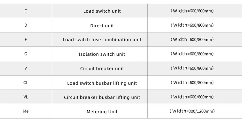
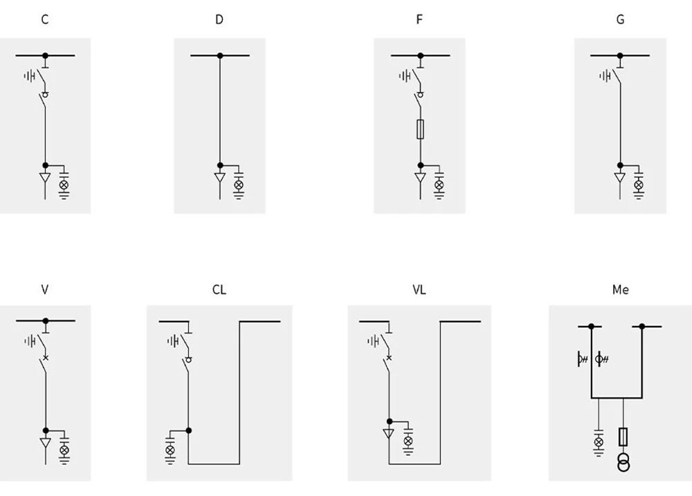
12KV 630A MV Gas Insulated Power Distribution Switchgear Basic Scheme
Operation Condition

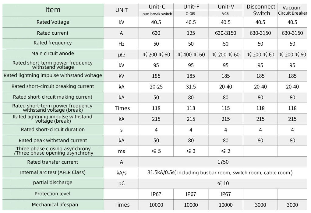
12KV 630A MV Gas Insulated Power Distribution Switchgear Technical Parameter
Grounding and Separation
The C-GIS gas-insulated high-voltage switchgear comes in various current levels ranging from 630A to 3150A. The cabinet size can be tailored to specific requirements. Constructed from aluminum zinc-coated plates and 304 stainless steel plates, the outer shell and gas box ensure durability. Each unit can be expanded and combined independently based on the design. The cabinet comprises a secondary control room, busbar room, circuit breaker room, circuit breaker operating mechanism room, and cable room. With a cable connection height of up to 700mm, maintenance and installation are made easier. Additionally, the cabinet features a comprehensive grounding protection system and includes isolated functional compartments like switch rooms, busbar rooms, cable rooms, and secondary circuit channels separated by grounding metal partitions for compartmental independence.
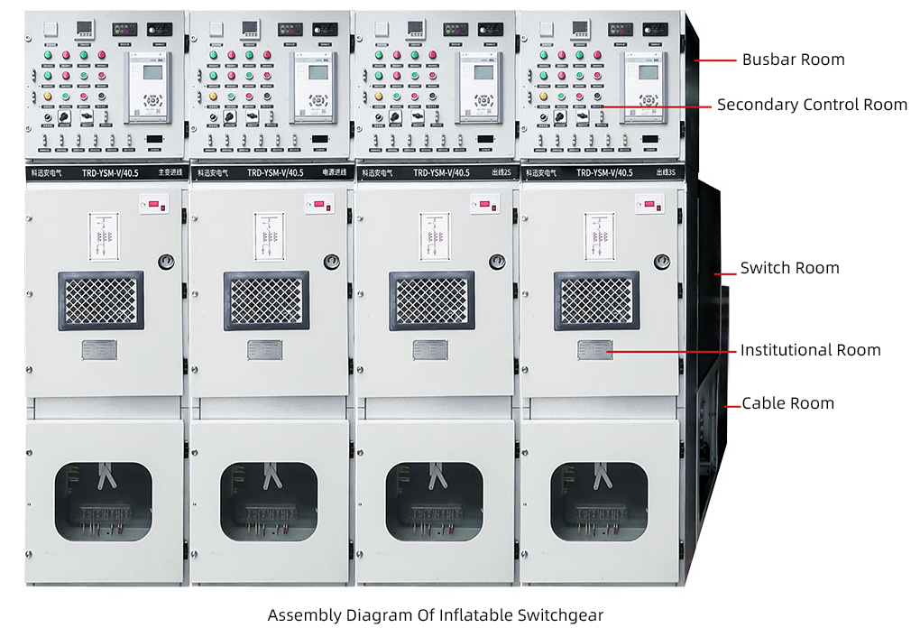
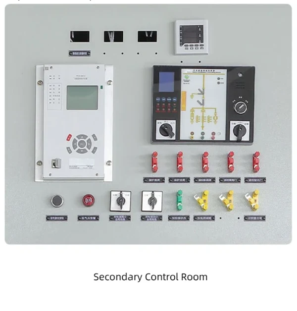
Secondary control room
The auxiliary control room, situated above the cabinet, boasts an array of component installation boards and terminal block fixing brackets. This space allows for the fitting of wiring terminals, small busbar terminals, comprehensive protection devices, and diverse control and operation devices, thereby enabling remote control, telemetry, remote signaling, and local monitoring capabilities. The secondary control room features circular holes at the corresponding positions of the left and right side panels, facilitating seamless cabinet connection.
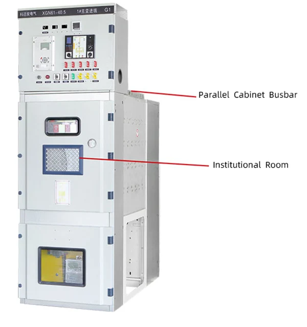
Busbar Compartment
The busbar room is situated within the upper air box along with the isolation mechanism. Once the cabinet is installed on the ground support, the left and right circuit cabinets and busbars are securely linked by merging the cabinets together.
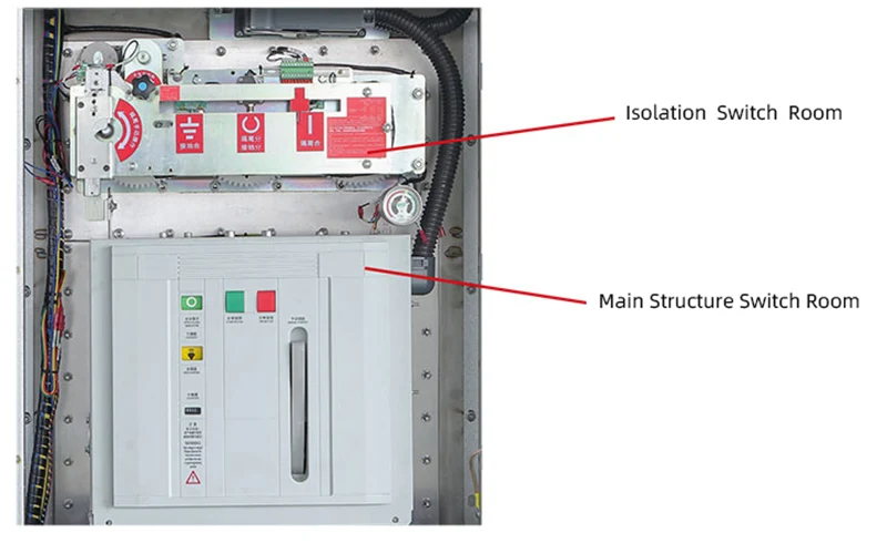
Switch Room
The switch room is located at the center of the cabinet, designed with a plate-type gas-insulated switch cabinet configuration comprising two chambers – one upper and one lower. Within the upper chamber, there is a three-position isolation switch, while the lower chamber houses a vacuum circuit breaker. The busbar, three-position isolation switch, and vacuum circuit breaker are positioned in an "up, middle, and down" arrangement. A single-chamber setup is straightforward, cost-effective, and easy to produce but may result in components interfering with each other and reduced reliability. On the other hand, a multi-chamber structure allows for easier component replacement, prevents mutual interference, and offers enhanced safety. However, the multi-chamber design is intricate, challenging to manufacture, and more expensive.
Institutional Room
TThe spring-driven system is positioned on a flat surface, with the isolation and circuit breaker systems kept separate. It is connected to the insulation rod of the vacuum arc extinguishing chamber, streamlining the transfer process. The operation of the system aligns better with the circuit breaker's opening and closing actions, leading to decreased power usage and enhanced mechanical dependability and adaptability.
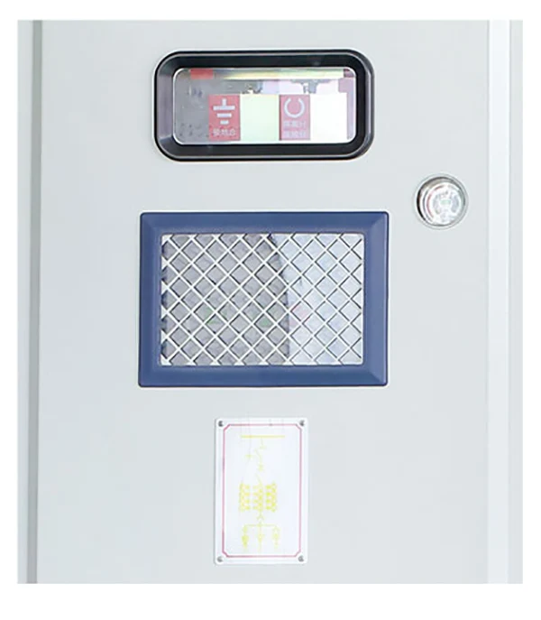
Cable Room
The cable room, located beneath the cabinet, features a separate pressure relief system. The cable connections to the ground can extend up to 700mm in height. To ensure proper grounding, interlocks have been installed in the cable room, allowing for the installation of two cables and lightning arresters in each circuit. Additionally, the incoming and outgoing cables and lightning arresters are securely connected using a specially designed internal cone insertion method.

Hot Tags: switchgear cost,11kv switchgear panels,132kv gis switchgear,66kv switchgear,control & switchgear co ltd,controls & switchgear company limited,electrical switchgear companies,general electric medium voltage switchgear,generation transmission and switchgear,hv gis
Product Tag
Related Category
Gas insulated switchgear
Medium Voltage Switchgear
Low Voltage Switchgear
Ring Main Unit RMU
Power transformer
Components
Cable Branch Cabinet
Wind Power Photovoltaic And Energy Storage
MV soft starter
Electrical Substation
Tools
Send Inquiry
Please Feel free to give your inquiry in the form below. We will reply you in 24 hours.