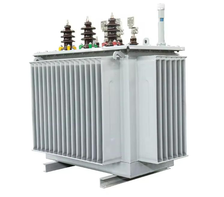
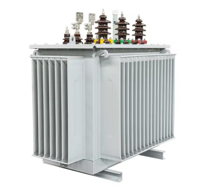
Outdoor transformer oil immersed transformer 10kv 20kv 35kv
Outdoor transformer oil immersed transformer 10kv 20kv 35kv are a newer type of transformer that boasts a better-designed structure and improved performance. Its three core columns, arranged in an equilateral triangle shape, eliminate any air gaps in the magnetic circuit, resulting in tighter windings. The length of the three magnetic circuits is consistent and shorter, and the cross-sectional area of the core columns is closer to a circle. These design improvements lead to enhanced performance, reduced loss, decreased noise, and a better balance of the three components. Additionally, the third harmonic component is reduced. This transformer is well-suited for use in urban and rural areas, industrial and mining enterprise power grids, and is ideal for combination transformers and pre-installed substations.
Model:oil-immersed transformer
Send Inquiry
Product Description
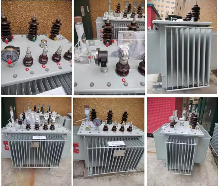
Outdoor transformer oil immersed transformer 10kv 20kv 35kv rely on oil for both insulation and cooling, with various cooling methods such as self-cooling, air-cooling, water-cooling, and forced oil circulation. The main components include an iron core, winding, oil tank, oil conservator, respirator, explosion-proof tube, radiator, insulation sleeve, tap changer, gas relay, thermometer, oil purifier, and more.
The silicon steel sheets in oil-immersed transformers have a unique interlayer, which allows the transformer oil to penetrate and play a buffering role, resulting in lower noise levels. However, the pressure-regulating switch, located inside the fuel tank, can be problematic if the contact is not good, leading to an open circuit or even switch burnout under high loads.
Operating temperature of Outdoor transformer oil immersed transformer 10kv 20kv 35kv
Oil-filled transformers are designed to function within specific cooling conditions, as indicated on the nameplate. It is important to ensure that the top oil temperature does not surpass 90 ℃ to maintain optimal performance and prevent insulation degradation. For regular operation, it is recommended to keep the top oil temperature below 85 ℃, with an alarm set at 80 ℃ to alert of any potential issues.
Overload
Transformers are designed to handle both normal overload and accidental overload situations, and it is recommended to have overload signals in place. In cases where overload signals cannot be installed, a comprehensive measuring device should be used instead. For oil-immersed transformers, the overload signal value should be set between 1.1 to 1.2 times the transformer's rated current. On the other hand, for dry-type transformers, the overload signal value should be between 1.2 to 1.3 times the rated current, taking into account the current of the fan during operation. It is important to monitor the load and temperature changes of the transformer once the overload signal is triggered. Regular inspections should be conducted to identify the cause of overload if circumstances allow. If the overload is significant (exceeding 1.3 times the rated current) or if the temperature surpasses the upper limit, the load should be reduced. Monthly data downloads and load analysis are essential when installing a comprehensive transformer. For transformers showing overload patterns, the data collection frequency should be increased, and load and temperature measurements should be taken during overload calculations. Prompt inspections and investigations should be carried out to determine the cause of overload whenever possible. If the transformer's load exceeds a critical threshold (1.3 times or more of the rated current) or if the temperature goes beyond the upper limit, the load must be decreased.
Cooling method
There are three primary cooling methods employed in oil-immersed transformers:
1. Oil-immersed self-cooling, which relies on the natural convection of oil to dissipate heat.
2. Oil-immersed air-cooled, which builds upon the self-cooling method and incorporates a fan to blow air onto the oil tank and pipes, thereby enhancing heat dissipation.
3. Forced oil circulation involves using an oil pump to extract hot oil from the transformer, cool it externally, and then return it to the transformer.
Structural function
The primary transformer in the primary substation of an urban rail transit power supply system is typically a three-phase oil-immersed transformer. This type of transformer comprises several key components, including an iron core, winding, oil tank, voltage regulating device, radiator, oil conservator, gas relay, insulation sleeve, explosion-proof tube, and other parts.
1. Iron core
The iron core is composed of silicon steel sheets with excellent magnetic conductivity stacked together, forming a magnetic flux shut circuit. The primary and second windings of the transformer are wound on the iron core. Transformer cores are separated into two sorts of structures: core type and covering type. Currently, the widely used transformers are all core frameworks. The heart kind iron core is made up of a south iron core column and an iron yoke. The iron core of an oil-immersed transformer has an oil flow for cooling the iron core, which assists in oil flow in the transformer and also improves the warmth dissipation result of the tools.
2. The winding
The winding, likewise referred to as the coil, is the conductive circuit of a transformer, which is wound with copper or aluminum cord to form a multi-layer round shape. The primary and the secondary winding is concentrically sheathed on the iron core column. For insulation functions, the low-voltage winding is normally positioned inside, and the high-voltage winding is placed outside. The insulation material is wrapped around the external edge of the cord to make certain insulation in between the cables and in between the cables and the ground.
3. The oil tank
The oil storage tank is the outer covering of an oil-immersed transformer, which is utilized not only to tank oil but also to set up various other elements.
4. Voltage regulation device
The voltage regulation device is readied to ensure the stability of the second voltage of the transformer. When the power supply voltage is modified, make use of a voltage regulating device to readjust the transformer faucet changer to make a certain stable outcome voltage on the additional side. The voltage regulation device is divided into two kinds: loaded voltage law tool and unloaded voltage regulation tool.
5. The radiator
The radiator is set up on the wall of the oil container, and the top and lower components are connected to the oil storage tank through pipes. When there is a temperature distinction between the top and lower oil temperatures of the transformer, oil convection is formed via the radiator. After cooling by the radiator, it flows back to the oil storage tank, playing a role in lowering the temperature of the transformer oil. To enhance the cooling impact, procedures such as self-air conditioning, required air cooling, and required water cooling can be embraced.
6. Oil conservator
Oil conservator, additionally known as oil conservator. Transformer oil will experience thermal growth and tightening because of temperature adjustments, and the oil degree will certainly additionally rise or fall with temperature modifications. The feature of the oil conservator is to supply a barrier room for the thermal development and contraction of the oil and to maintain the oil storage tank constantly filled with oil. At the same time, as a result of the presence of an oil conservator, the get-in-touch with a location in between oil and air is reduced, which can decrease the oxidation of the oil.
7. Gas relay
Gas relay, additionally known as gas relay, is the main protective device for interior mistakes in transformers. It is installed in the middle of the connecting oil pipe between the oil tank and the conservator. When a major mistake takes place inside the transformer, the gas relay links to the breaker and trips in the same circuit. When a minor fault takes place inside the transformer, the gas relay links to the mistake signal circuit.
8. The high and low insulation sleeves
The low and high insulation sleeves lie on the top cover of the transformer oil tank, and ceramic insulation sleeves are generally used for oil-immersed transformers. The feature of the insulation sleeve is to maintain good insulation in between the low and high-voltage winding leads and the oil tank and to repair the leads.
9. Explosion proof tube
The explosion-proof tube, likewise called the safety and security respiratory tract, is installed on the oil tank of the transformer, and its electrical outlet is sealed with glass explosion-proof movie. When a major malfunction takes place inside the transformer, and the gas relay falls short, the gas inside the oil tank appears in the glass explosion-proof movie and sprays out of the safety air passage to prevent the transformer from taking off.. Insulation structure
Transformer insulation effect
( 1) Shield the conductive body from various other parts.
( 2) Can separate various charged components.
( 3) A practical insulation setup can improve the uniformity of electric area circulation.
( 4) Enable electric parts to attain a certain amount of capacitance.
( 5) Plays a role in mechanical assistance, fixation, and oil flow for heat dissipation.
Insulation classification and requirements for Outdoor transformer oil immersed transformer 10kv 20kv 35kv
1.Classification of insulation for transformers
The transformer's insulation system can be categorized into two parts: internal and external insulation. Internal insulation encompasses the various components inside the oil tank, while external insulation refers to the insulation between the bushing and ground, as well as between each other. The internal insulation can be further divided into two sub-categories: main insulation and longitudinal insulation. The main insulation is responsible for insulating the winding and grounded parts, as well as the spaces between windings. In oil-immersed transformers, the oil paper barrier insulation structure is the most commonly used main insulation.
The main insulation can be further classified into graded and full insulation. Graded insulation refers to the main insulation level near the neutral point being lower than the insulation level at the ends of the winding. Conversely, full insulation occurs when the insulation level at the first and last ends of the transformer is the same. Additionally, vertical insulation refers to the insulation between different parts of the same winding, such as the insulation between wire turns, turns, and turns.
2.Insulation requirements for transformers
The need for transformer insulation is to not affect the normal procedure of the transformer as a result of insulation damage throughout the operating duration. Its major needs are as complies with.
( 1) Efficient in enduring overvoltage and regular operating voltage throughout the operation.
( 2) Capable of withstanding short-circuit existing, overcurrent, and typical operating current during operation.
( 3) The level of moisture and aging does not impact the typical procedure of the transformer.
3.Insulation Materials for Transformers
The major insulation materials inside transformers consist of transformer oil, insulating cardboard, wire paper, telephone paper, and old and wrinkly paper.
( 1 )Transformer oil.
( 2 )Shielded cardboard. Insulating cardboard is primarily made by pushing unbleached sulfate fibers, which have a lot of pores in between the fibers, hence having strong breathability, oil absorption, water absorption, etc. Suppose high heat-resistant polyamine fiber paper is used. In that case, its lifespan will certainly be substantially enhanced, for example, as an insulating paper tube, support bar, cushion block, dividing, corner ring, etc.
( 3 )Cable paper. This insulation paper is made of sulfate pulp and is used in transformers with cable television paper versions DL2-08 and DL2-12, with densities of 0.08 mm and 0.12 mm. It is mainly utilized for insulation on the external surface of cords, interlayer insulation of coils, and lead wrapping insulation. It is just one of the major insulation products for oil-immersed transformers.
( 4 )Telephone paper. Made from sulfate pulp. Use telephone paper with design DH-50 in the transformer. Its density is (0.5 ± 5%) mm, and it is rolled into a paper roll with a width of (500 ± 10) mm. Generally used for insulation of coil cables and finish insulation of coils.
( 5 )Wrinkle paper. It is also insulation paper, made from cord paper made from sulfate pulp and processed. It has excellent electrical efficiency in oil, characterized by high ordinary failure voltage and little tangent worth of dielectric loss angle. Wrinkle paper is mainly used for wrapping transformer outbound lines and other areas.
The dielectric coefficient of insulating paper and cardboard, denoted as ε, is in the range of 4-5, surpassing the dielectric coefficient of transformer oil, represented as ε=2.2, by more than double. In composite insulation, the field strength experienced is inversely related to the dielectric coefficient of the material when subjected to an electric field.
The field strength within the oil gap is significantly stronger than that of cardboard, making it a vulnerable point in the insulation of oil paper. As a result, researchers are exploring new types of cardboard with lower dielectric coefficients to reduce the size of the insulation structure in transformers.
Introduction to Insulation Structure
Main insulation structure for Outdoor transformer oil immersed transformer 10kv 20kv 35kv
1. Between winding and iron core
The iron core consists of a core pillar and an iron yoke that are grounded while in operation. The insulation between the winding and the core pillar is primarily provided by the winding near the core pillar. Illustrated in Figure 2-15, an insulated paper cylinder and a cylindrical iron core are utilized for this purpose. To create a specific thickness of oil gap insulation, a support strip is placed between the outer diameter of the paper tube and the inner diameter of the winding, as demonstrated in Figure 2-18. In scenarios of high voltage, the paper tube support strip can be recycled to generate an additional layer of insulation, as depicted in Figures 14 and 16 within Figure 2.
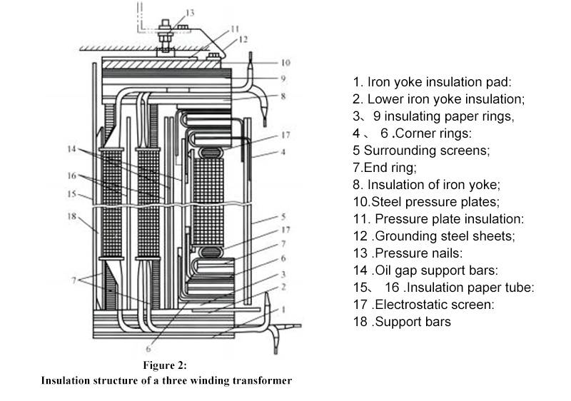
The iron core consists of a core pillar and an iron yoke that is grounded while in operation. The winding near the core pillar primarily provides the insulation between the winding and the core pillar. Illustrated in Figure 2-15, an insulated paper cylinder and a cylindrical iron core are utilized for this purpose. To create a specific thickness of oil gap insulation, a support strip is placed between the outer diameter of the paper tube and the inner diameter of the winding, as demonstrated in Figure 2-18. In scenarios of high voltage, the paper tube support strip can be recycled to generate an additional layer of insulation, as depicted in Figures 14 and 16 within Figure 2.
2.Between windings
Paper tube oil gap insulation is commonly utilized as the primary insulation method for windings levels within the same phase or across different phases. This type of insulation is frequently seen in high-capacity ultra-high voltage transformers, where thin paper tubes with minimal oil gaps are commonly employed.
3.Between the winding and the casing
The outermost winding and the oil tank provide the primary insulation between the winding and the casing. At voltage levels of 110kV or lower, the insulating oil provides sufficient thickness for the main insulation. In contrast, at higher voltages of 220kV and above, an additional cardboard screen is incorporated to reinforce the main insulation between the ground and the winding.
4. Insulation of outgoing lines
The thickness of the crumpled paper covering the coiled edge changes depending on the voltage levels. More voltage results in a thicker layer of crumpled paper. Wrap crumpled paper of the right thickness close to the edge of the coil, but not directly on it, using a bare cable or metal busbar. Then, weld a multi-layer soft copper wire that is directly linked to the porcelain sleeve.
5. Insulation of tap changer
The tap changer's operating rod acts as a crucial insulator between the high and medium-voltage windings and the ground. This is because one end of the rod connects to the high and medium-voltage parts while the other end attaches to the casing, which is grounded. Typically, the operating rod is crafted from phenolic insulation paper tubes or dried wood coated with protective paint. It is mounted on an insulation bracket, with the conductive part providing insulation between the bracket and the ground. The primary insulation is constructed from southern wood or phenolic cardboard.
6. External main insulation of transformers
The transformer's insulation sleeve is designed to guide the high and low-voltage leads from inside the transformer to the exterior of the oil tank. It provides both insulation for the leads to the ground and structural support as a fixed lead. Thus, meeting the electrical and mechanical strength requirements specified in manufacturing standards is crucial. The conductor within the ceramic bushing of a transformer is a critical component that carries current during normal operation and short circuits. As a result, the ceramic bushing must possess strong thermal stability. The design and materials used in the insulation sleeve are determined based on the voltage level requirements.l.
Vertical insulation
Vertical insulation involves providing insulation between individual turns, layers, and screens within the same winding coil; there are multiple winding turns, necessitating insulation between them. The inter-turn insulation typically consists of cable paper encasing the wire, with thicker insulation required for higher voltage levels. Interlayer insulation pertains to the insulation between adjacent wire layers, equivalent to the oil passage width..
Hot Tags: transformer,transformere,transformer 6,electrical transformers,current transformer
,step down transformer,a step down transformer,transformer type,step up transformer,power transformer
Product Tag
Related Category
Gas insulated switchgear
Medium Voltage Switchgear
Low Voltage Switchgear
Ring Main Unit RMU
Power transformer
Components
Cable Branch Cabinet
Wind Power Photovoltaic And Energy Storage
MV soft starter
Electrical Substation
Tools
Send Inquiry
Please Feel free to give your inquiry in the form below. We will reply you in 24 hours.